

A roof curb DWG is a two-dimensional AutoCAD drawing file that defines the geometry, material specifications, attachment details, and dimensional tolerances of a fabricated roof curb assembly. Unlike a preview image or a low-resolution PDF, a DWG is an editable vector file: the engineer can extract dimensions, verify clearances against the structural model, and feed curb geometry directly into a BIM coordination workflow.
On fast-track design-build projects, particularly mission-critical facilities where mechanical equipment sets are large and submittal cycles are compressed, getting a stamped, fully dimensioned DWG from the fabricator early is not a courtesy. It is a schedule dependency.
This post covers what a roof curb DWG contains, which file formats a design-development package typically requires, how to read the key elements of a curb detail, where curb DWGs sit in CSI MasterFormat, and how to request a stamped detail from a fabricator.
What File Format Should You Request: DWG, DXF, RFA, or IFC?
The answer depends on where you are in the project and who needs the file.
| Format | What it is | When to request it |
|---|---|---|
| DWG | Native AutoCAD binary; universal 2D detail format | 60% DD through construction documents; submittal package standard |
| DXF | ASCII exchange format; opens in nearly any CAD platform | When the team runs non-Autodesk software or the DWG produces translation errors |
| RFA | Revit Family file; 3D parametric object for BIM models | When the BIM Execution Plan requires LOD 300 curb geometry in the Revit model |
| IFC | Open BIM format; platform-neutral 3D exchange | International projects or owner-mandated open-BIM workflows |
For most commercial and mission-critical design-development packages in the United States, DWG is the baseline request. The RFA becomes relevant when the BIM coordinator’s LOD schedule, documented per AIA E203-2013 and AIA G202-2013, requires curb elements at LOD 300 or higher.
LOD 300 means the element is graphically represented with accurate quantity, size, shape, location, and orientation: the level at which clash detection and MEP coordination become reliable. That is the standard threshold for curb geometry at design development. LOD 350 adds interface data with adjacent systems, relevant when the curb detail must coordinate with deck attachment, structural framing, or roofing membrane termination.
Note for mission-critical projects: on data center and other large-equipment builds where multiple curb types (base curbs, spring isolation curbs, and equipment covers) are specified simultaneously, request DWG files for each curb type in the same submittal package. Coordinating geometry across all three in one pass eliminates a common source of submittal revision cycles.
What Does a Roof Curb DWG Actually Contain?
A well-structured curb DWG delivered by a fabricator covers eight elements. Use this table to evaluate any file before it goes into your submittal package.
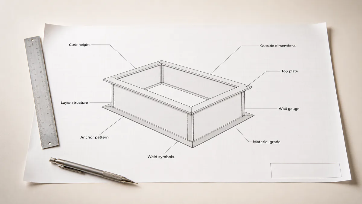
What to Verify in Any Roof Curb DWG Before Submittal
| DWG element | What a compliant detail shows | What to check |
|---|---|---|
| Curb height | Minimum 8" above finished roof membrane; 14" is the common standard for rooftop HVAC units | Confirm height accounts for insulation thickness above deck. The 8" minimum is measured from finished membrane, not bare deck |
| Overall outside dimensions | Length x width matching the HVAC manufacturer’s curb specification exactly | Pull the unit manufacturer’s curb spec and verify. A 1/4" discrepancy means the unit won’t seat correctly |
| Top plate | Level and square across the full bearing surface. Equipment manufacturers require a level curb prior to unit installation | An unlevel top plate creates vibration, accelerates wear, and voids most equipment manufacturer warranties |
| Wall gauge | 16 ga standard for commercial rooftop applications; 14 ga for heavy equipment or elevated load conditions | Verify gauge against equipment weight. Lighter gauges are not appropriate for large CRAC/CRAH units |
| Material and coating callout | Galvanized steel per ASTM A653; G90 coating (0.90 oz/ft² zinc, both sides) for rooftop exposure | G60 is not adequate for exposed rooftop service. G90 provides approximately 50% longer service life than G60 outdoors |
| Weld symbols | Continuous fillet weld callouts at corner seams, base plates, and top flanges per ANSI/AWS A2.4 | A DWG without weld symbols leaves corner construction open to interpretation. Fully welded and knockdown curbs are not interchangeable on a mission-critical submittal |
| Attachment callout | Anchor bolt pattern: diameter, spacing, edge distance, and deck interface (B-deck, standing seam, or structural deck) | Verify attachment matches your structural deck type. A detail drawn for B-deck does not transfer to a standing seam roof |
| Layer structure | NCS/AIA CAD Layer Guidelines: mechanical equipment elements on M-discipline layers; no geometry on a single unlabeled layer | Run a layer audit before importing. Single-layer files require manual cleanup that kills coordination time |
A DWG missing any of these elements is not submittal-ready. It is a drafting file that someone else has to finish.
Where Does the Roof Curb DWG Live in CSI MasterFormat?
Roof curb specifications and their associated drawings coordinate under CSI MasterFormat 2020 Section 07 72 13, Manufactured Curbs, within Division 07 (Thermal and Moisture Protection).
The DWG accompanies the Division 07 72 13 submittal package. The curb’s mechanical attachment, the hardware connecting curb to structural deck, may also be cross-referenced in Division 05 (Metals) or Division 23 (HVAC) depending on how the project manual is organized. When in doubt, include a cross-reference note in Section 07 72 13 directing reviewers to the mechanical section for HVAC unit specifications.
How to Request a Stamped Roof Curb DWG
Submittal reviewers need a stamped detail: a drawing that carries the fabricator’s revision block, drawing number, and material callouts in a format that can be signed off. A preview image does not satisfy this requirement.
To get a usable DWG from a custom fabricator, provide:
- Equipment data: the HVAC manufacturer’s curb specification for the selected unit, including base dimensions and opening size. On data center projects, this typically means CRAC or CRAH unit specs, often in quantities that require coordinated DWG packages across multiple curb types and roof zones.
- Roof geometry: roof type (flat deck, standing seam, exposed fastener panel), slope if applicable, and structural deck profile.
- Attachment environment: wind zone and seismic design category relevant to the project location.
- Format requirement: specify DWG, DXF, or RFA, and name the LOD required if an RFA is needed for BIM coordination.
Custom Curb designs all drawings in-house from customer-provided specifications, no site visit required. The DWG is produced as part of the standard quoting and submittal workflow.
For data center and mission-critical projects requiring vibration isolation, where CRAC and CRAH units sit on spring isolation curbs rather than standard base curbs, the submittal package also includes spring deflection calculations. See our spring isolation curbs page for the engineering requirements.
Frequently Asked Questions
What is the minimum height a roof curb DWG should show?
The minimum curb height for roof-mounted mechanical units is 8 inches above the finished roof membrane, consistent with NRCA guidelines and a standard reflected across most US building codes. On projects with thick tapered insulation, verify the 8" is measured from the finished membrane surface, not the bare deck. The difference can be significant on a heavily insulated data center roof.
What format and version should I specify when requesting a curb DWG?
When requesting a DWG, specify the AutoCAD version your office standard requires. Common requests are 2018, 2020, or 2022 format. If your team runs non-Autodesk software, request DXF instead: it opens in virtually any CAD or BIM platform without translation errors. A fabricator worth working with will accommodate either format without friction.
What is LOD 300, and does a roof curb DWG meet that requirement?
LOD 300, as defined by AIA/BIMForum, means a model element is represented with accurate size, shape, location, and orientation, sufficient for clash detection and MEP coordination. A well-structured 2D DWG provides the dimensional data to build an LOD 300 Revit family, but the RFA file itself is what goes into the model. If the BIM Execution Plan requires a native RFA, request that format directly from the fabricator.
Where does the roof curb DWG fit in the submittal package?
The curb drawing is part of the Division 07 72 13 submittal, submitted alongside material certifications and, on spring isolation curbs, spring deflection calculations. The full submittal review process, including 30%-60%-90% DD review gates, is covered in our roof curb installation and submittals guide.
Why does the G90 coating designation matter on a roof curb DWG?
G90 is the ASTM A653 designation specifying 0.90 oz/ft² of zinc coating on both sides, the standard for exposed rooftop fabrication. A G90 coating provides approximately 50% longer service life than G60 in outdoor exposure. A DWG that calls out "galvanized" without the G90 designation leaves the coating weight open to interpretation at the fabrication stage.
Need a stamped roof curb DWG for your project?
Contact Custom Curb with your unit manufacturer’s curb spec and roof geometry. All drawings are produced in-house, no site visit required.